Split 100G into 4×25G
Goal
The goal of the steps below is to configure the switch to split each 100G interface into 4 interface each capbable of 25G.
This way, the switch can work well with the existing 4 X 25G sfp pcie cards.
Steps Before Using the Switch
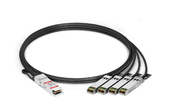
Step 1: Connect the Breakout Cable
-
Connect one end of the breakout cable to the switch 100G port.
-
The other end should connect to the PC, split between the PCIe network cards.
-
Each network card should have two cables connected.
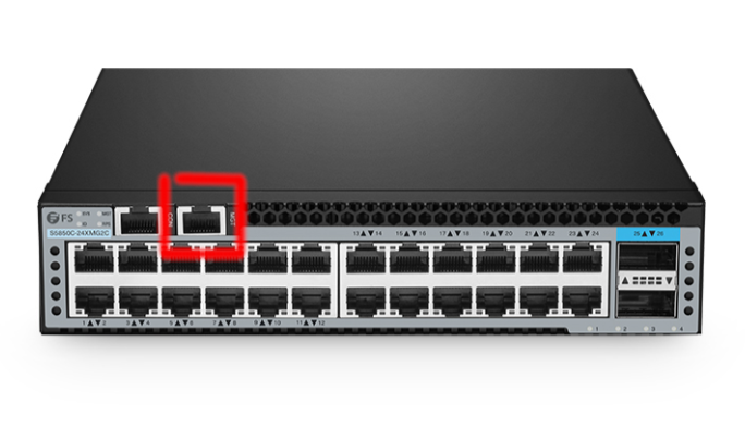
Step 2: Connect a Laptop for Configuration
-
Use an ethernet cable to connect your laptop directly to the switch.
-
The switch has a port marked MGT (management). Connect the cable there and to your laptop.
-
Once configuration is done, this cable can be disconnected.
Step 3: Set Laptop IP Address
-
By default, the switch uses IP 192.168.1.1.
-
Set your laptop LAN IP to the same range (e.g., 192.168.1.10).
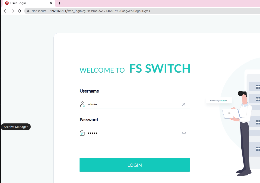
Step 4: Access the Web Management Interface
-
Open a browser and navigate to 192.168.1.1.
-
You should see the web-based management system of the switch.
Step 5: Login to Web Interface
-
Use the following credentials:
-
User: admin
-
Password: admin
-
Switch Configuration via Terminal
Step 6: Open a Terminal
-
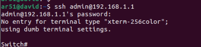
On your laptop, open PuTTY (or another SSH client).
-
Connect to the switch:
ssh admin@192.168.1.1 -
Password: admin
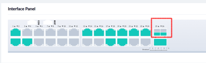
Step 7: Split the 100G Interfaces
-
The switch has two 100G interfaces.
-
We need to split each into 4 × 25G for use with the breakout cable.
Run the following commands:
configure terminal

split interface eth-0-25 25G

split interface eth-0-26 25G

exit

write memory

reload
- Press Enter to confirm the reboot.
Summary
At the end of this process, you should have the 100G interface splitted into 4 interfaces.